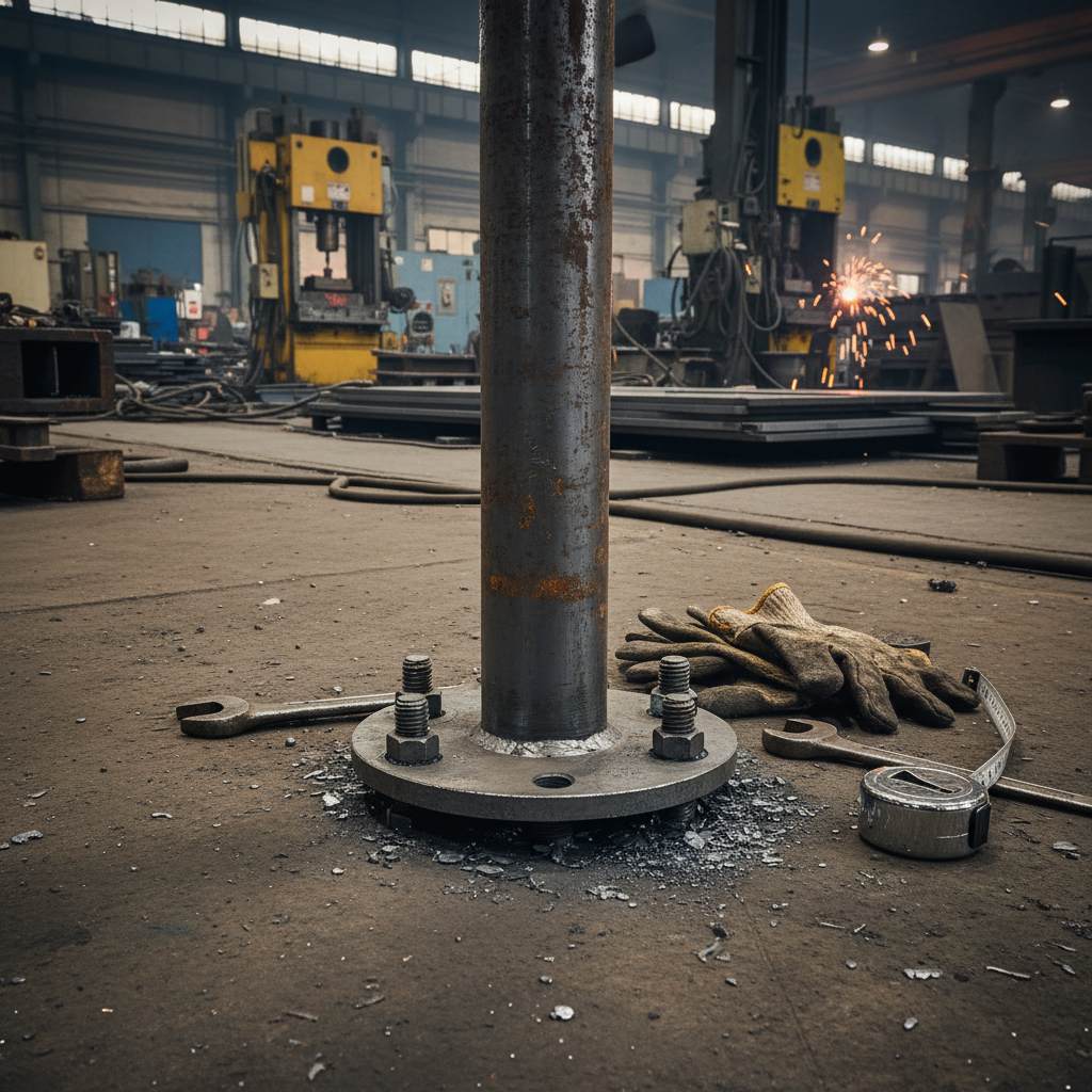
Selecting the right connection components for high-pressure piping systems is often a matter of balancing structural integrity with long-term operational safety. In environments where thermal expansion and extreme pressures are constant variables, the geometry of the joint becomes the primary line of defense against fatigue and failure.
The complexity of modern industrial infrastructure—ranging from offshore oil platforms to nuclear power plants—demands components that can distribute mechanical stress evenly while minimizing turbulence. This is where the technical distinction between standard fittings and specialized high-performance components becomes critical for system longevity.
When auditing flange suppliers, engineers must look beyond basic material certifications to evaluate how specific designs, such as the Long Neck Flange, mitigate risk in volatile environments.


The Long Neck Flange, frequently categorized under weld-neck flanges, is defined by its distinct beveled end. This geometry is not merely for fitment; when the flange is flush to the pipe, it creates a precise trough that facilitates a full-penetration weld, ensuring the joint is as strong as the pipe itself.
Unlike slip-on variants, this design is engineered specifically for high-pressure and high-temperature applications. By transitioning the load from the flange ring to the pipe wall through a reinforced neck, it prevents the concentration of stress at the weld toe, which is the most common point of failure in pressure piping.
The core technical advantage of the Long Neck Flange lies in its tapered hub. This gradual transition between the flange face and the pipe diameter acts as a mechanical buffer. In systems subject to cyclic loading or thermal shock, this taper allows for a more uniform distribution of stress, significantly reducing the risk of deformation or cracking at the interface.
Beyond stress management, the hub design plays a vital role in fluid dynamics. By smoothing the internal transition, it minimizes turbulence and erosion at the joint. In high-velocity flows, turbulence can lead to localized pitting and wall thinning; the long neck geometry ensures a more stable flow profile, extending the service life of the entire pipeline.
From a manufacturing perspective, achieving this taper requires precision forging or casting. HEBEI JIUYUAN PIPELINE MANUFACTURING CO.,LTD utilizes advanced production facilities to ensure that the hub dimensions strictly adhere to standards such as ASME, DIN, and JIS, providing a consistent fit that simplifies field installation and enhances weld quality.
Material selection is governed by the chemical nature of the medium and the operating temperature. Carbon steels like ASTM A105 or P235GH are standard for non-corrosive high-pressure services, while stainless steels (ASTM A182/304/306) are mandatory for environments where oxidation or chemical attack is a concern.
The integrity of a pressure joint depends on the synergy between the material's yield strength and the flange's geometric ability to distribute stress; a failure in either leads to catastrophic leakages in hazardous environments.
To further enhance durability, surface coatings are applied based on the installation site. Options include black paint for general industrial use, galvanization for moisture-prone areas, or epoxy paint for highly corrosive chemical zones. These coatings act as a sacrificial or barrier layer, protecting the base metal from atmospheric degradation.
When comparing different flange types, the Long Neck design consistently outperforms others in high-stress categories. By evaluating the "Stress Concentration Factor," we can see how the tapered hub reduces the peak stress at the weld joint compared to flat-face or slip-on designs.
The following index illustrates the relative performance of various flange geometries across five key mechanical dimensions, where a higher value indicates better performance in managing the specific stressor.
In the oil and gas sector, these flanges are indispensable for upstream and downstream operations. On offshore platforms, where pipes are subject to constant vibration and saltwater corrosion, the robust weld-neck design ensures leak-proof connections that are vital for the safe transport of hydrocarbons.
Similarly, in power generation, thermal and nuclear plants utilize these components to connect high-pressure steam lines to turbines and boilers. The ability to withstand extreme temperature swings without losing structural integrity makes them the primary choice for heat exchangers and high-pressure water systems.
The manufacturing of pressure vessel components is increasingly moving toward stricter quality control and traceability. Modern standards such as ISO 9001:2008 and specialized pressure pipeline certifications are no longer optional but are baseline requirements for industrial safety.
There is a growing trend toward the use of duplex steels and nickel-based alloys to handle increasingly corrosive chemicals in petrochemical reactors. These materials require specialized forging temperatures and cooling rates to prevent phase separation, necessitating a higher level of technical expertise from the manufacturer.
Future developments are focusing on "intelligent" piping, where the flange interface may eventually incorporate sensors for real-time leak detection and stress monitoring. This shift will require flange suppliers to integrate precision machining with sensor-compatible geometries.
Procuring the correct flange requires a systematic evaluation of the operating environment. A common mistake in procurement is prioritizing cost over the pressure class (PN6 - PN40 or Class 150 - 2500), which can lead to premature failure under surge pressures.
The decision-making process should follow a hierarchy: first, define the medium and temperature to select the material; second, determine the pressure rating; and third, evaluate the joint frequency to decide between a standard weld-neck and a Long Neck variant.
The following table provides a comparison framework for evaluating different flange options based on common industrial requirements.
| Operational Driver | Recommended Design | Critical Parameter | Risk of Wrong Choice |
|---|---|---|---|
| Extreme Thermal Cycling | Long Neck Flange | Taper Hub Angle | Stress Cracking |
| High Chemical Corrosion | Stainless/Alloy Steel | Material Grade (A182) | Pitting/Perforation |
| Rapid Installation | Slip-on Flange | Weld Fillet Size | Joint Leakage |
| Ultra-High Pressure | Weld-Neck (Class 2500) | Wall Thickness | Catastrophic Burst |
| Low Pressure/Water | Flat Face Flange | Gasket Compatibility | Seal Deformation |
| High Velocity Flow | Long Neck Flange | Internal Bore Finish | Internal Erosion |
While both are weld-neck types, the Long Neck Flange features an extended tapered hub. This increased length provides a more gradual transition from the flange face to the pipe, which is critical for better stress distribution in systems with extreme temperature fluctuations or high mechanical vibration. This design minimizes the stress concentration at the weld joint, significantly reducing the likelihood of fatigue failure compared to shorter hubs.
For corrosive environments, stainless steels such as ASTM A182, 304, or 306 are preferred due to their chromium and nickel content, which forms a protective oxide layer. In extremely aggressive chemical settings, nickel-based alloys or duplex steels may be required. The choice depends on the specific chemical medium; for instance, some acids require high molybdenum content to prevent pitting corrosion.
The choice depends on the engineering standard being followed. PN (Pressure Nominal) is the European (DIN/EN) standard, typically ranging from PN6 to PN40. Class is the American (ASME) standard, ranging from Class 150 to Class 2500. If your system is designed according to ASME B16.5, you must use Class ratings. Mixing these standards can lead to incompatible bolt patterns and seal faces, resulting in dangerous leaks.
The bevel provides a V-shaped groove when aligned with the pipe end. This allows the welding electrode to penetrate the full thickness of the flange and pipe wall, creating a full-penetration weld. Without this bevel, the weld would only be superficial, creating a structural weak point that could fail under the high pressures typical of refineries or power plants.
Surface coatings prevent the base metal from reacting with the environment. Galvanization provides zinc protection against moisture, while epoxy coatings are designed to resist chemical splashes and industrial pollutants. Without proper coating, carbon steel flanges will oxidize, leading to surface pitting which can eventually compromise the structural integrity of the flange ring and the tightness of the bolted joint.
Technically, yes, but it is rarely cost-effective. Long Neck Flanges are over-engineered for low-pressure water systems. A simple slip-on or threaded flange would be sufficient and more affordable. The primary value of the Long Neck design—stress distribution and turbulence reduction—is only realized in high-pressure, high-velocity, or extreme temperature scenarios.
The technical superiority of the Long Neck Flange is not found in its simplicity, but in its ability to handle the invisible forces of thermal expansion and mechanical stress. For industries where a single joint failure can lead to catastrophic environmental or safety incidents, investing in precision-engineered components is a necessity rather than an option.
As pressure vessel standards continue to evolve, the synergy between advanced material science and optimized geometry will remain the cornerstone of pipeline reliability. By focusing on the mechanical fundamentals of stress distribution and material compatibility, operators can ensure a safer and more efficient industrial lifecycle.

 Albanian
 Arabic
 Armenian
 Azerbaijani
 Belarusian
 Bengali
 Bulgarian
 Croatian
 Czech
 Danish
 Dutch
 Esperanto
 Finnish
 French
 German
 Greek
 Hebrew
 Hungarian
 Indonesian
 Irish
 Italian
 Japanese
 Khmer
 Korean
 Kyrgyz
 Lao
 Latin
 Lithuanian
 Malay
 Myanmar
 Norwegian
 Persian
 Polish
 Portuguese
 Romanian
 Russian
 Serbian
 Slovak
 Slovenian
 Spanish
 Swedish
 Tagalog
 Thai
 Turkish
 Turkmen
 Uzbek
 Vietnamese
 Zulu
 English